1. Introduction to CCNA Exam
Exam Topics
CCNA Exam TopicsExam Instructions
Cisco Exam Tutorial
Question Types
CCNA Question TypesYOU CAN’T GO BACK AFTER ANSWERING OR SKIPPING A QUESTION.
Online Testing
Online TestingA PRIVATE and QUITE place for AT LEAST 2 HOURS must be needed.
Cisco Packet Tracer Installation
Cisco Packet Tracer Installation (Login First)Schduling and Taking the Exam
Scheduling And Taking the ExamExam Prep: Binary Game
Binary Game2. Network Devices
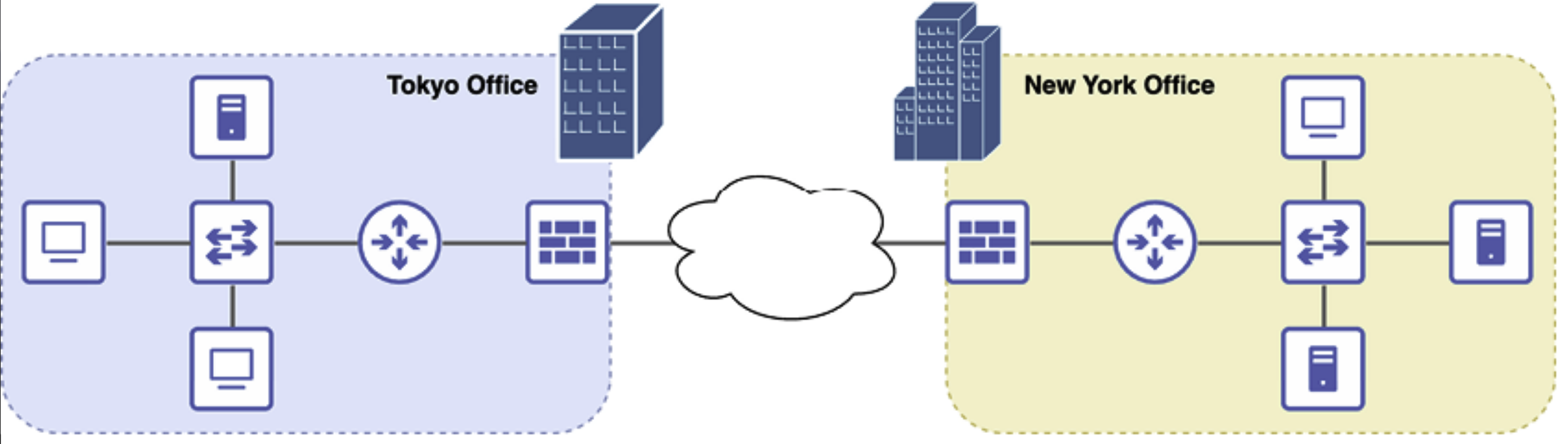
- Local Area Network (LAN): A network that connects computers and devices within a limited geographical area, such as a home, office, or school.
- Wide Area Network (WAN): A network that spans a large geographical area, often connecting multiple LANs.
- Computer Network: A system of interconnected computers and devices that communicate and share resources.
- Node: Any device connected to a network, such as a computer, printer, or phone.
- Resources: Assets shared over a network, including hardware (e.g., printers, storage) and software (e.g., applications, files).
- Client-Server: A network model where clients request services or resources from servers.
- Switches Devices provide connectivity between devices in a local area network (LAN).
- Routers: Devices that provide connectivity between LANs or external network.
- Wireless Router: A device that provides wireless connectivity to a network, allowing devices to connect without physical cables.
- Network Firewall: A security system that monitors and controls incoming and outgoing network traffic based on predefined security rules, protecting against unauthorized access.
3. Cables, Connectors, and Ports
- Ethernet: A widely used wired networking technology that connects devices in a LAN using cables such as twisted pair or fiber optics. It follows standards like IEEE 802.3.
- IEEE (Institude of Electrical and Electronics Engineers): An organization that defines networking standards, including Ethernet (IEEE 802.3) and Wi-Fi (IEEE 802.11).
- Unshilded Twisted Pair (UTP) Cables: A type of Ethernet cable with twisted copper wire pairs that reduce electromagnetic interference (EMI). Common categories include Cat5e, Cat6e, and Cat6a.
- Shielded Twisted Pair (STP) Cables: A type of Ethernet cable that includes additional shieding to protect against electromagnetic interference (EMI) and crosstalk (an interference caused by signal leakage between adjacent cables or wire pairs in a network).

UTP Cables vs. STP Cables - Electromagnetic Interference (EMI): Disruptions in signal transmission caused by external electromagnetic sources, such as power lines or other electronic devices. Shielded cables (STP) help reduce EMI.
- 8 Position 8 Contact (8P8C) Connector: The standard modular connector used for Ethernet cables, often incorrectly called an RJ45 connector.

8P8C vs. RJ45 - Fiber Optic Cables: High-speed network cables that use light instead of electrical signals, offering faster speeds and resistance to EMI.

Fiber Optic Cable Structure - Single Mode Fiber (SMF): A fiber optic cable type designed for long-distance transimission using a single light beam, reducing signal loss and allowing for higher speeds.
- Multimode Fiber (MMF): A fiber optic cable type that carries multiple light beams, suitable for shorter distances due to higher dispersion.

Single Mode vs. Multimode
4. Networking Models
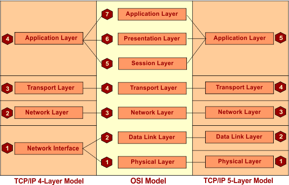
Networking models are conceptual models that define how different layers of a network should interact to achieve communication between devices. The two most common models are the OSI Model and the TCP/IP Model.
The OSI Reference Model
The OSI (Open Systems Interconnection) Model is a conceptual framework that divides network communication into seven layers. These layers are the Physical Layer, Data Link Layer, Network Layer, Transport Layer, Session Layer, Presentation Layer, and Application Layer. Each layer has a specific function and interacts with adjacent layers to ensure smooth and efficient data transmission.
- Physical Layer: Transmits raw bits over a physical medium (e.g., cables).
- Data Link Layer: Handles data frames and ensures error-free transmission between adjacent nodes (e.g., MAC addresses, switches).
- Network Layer: Determines the best path for data and handles addressing and routing (e.g., IP addresses, routers).
- Transport Layer: Ensures reliable data transfer with error correction and flow control (e.g., TCP, UDP).
- Session Layer: Manages and controls communication sessions between applications.
- Presentation Layer: Converts data formats for compatibility (e.g., encryption, compression).
- Application Layer: Provides network services directly to applications (e.g., HTTP, FTP, SMTP).
The TCP/IP Model
The TCP/IP Model (Transmission Control Protocol/Internet Protocol) is a practical framework used for internet communication. It consists of four layers: the Network Interface Layer, Internet Layer, Transport Layer, and Application Layer.
- Network Interface Layer: Handles physical data transmission over a network medium. It is equivalent to the Physical and Data Link Layers of the OSI model.
- Internet Layer: Routes packets across networks using IP addresses, similar to the Network Layer in the OSI model.
- Transport Layer: Ensures reliable (TCP) or fast (UDP) data delivery between devices, corresponding to the Transport Layer in the OSI model.
- Application Layer: Supports network applications and protocols like HTTP, FTP, and SMTP. It combines the functions of the Application, Presentation, and Session Layers in the OSI model.
The 5-Layer Network Model
The 5-Layer Network Model is a simplified version of the OSI Reference Model, commonly used to understand networking concepts. It merges the Session, Presentation, and Application Layers of the OSI model into a single Application Layer. Below is the diagram illustrating this model:
Key Notes
- In networking, adjacent layer interaction refers to the communication and collaboration between two neighboring layers in a networking model. Each layer provides service to the layer above it and relies on the layer below it to perform its functions.
5. The Cisco ISO CLI
EXEC, Privileged EXEC, and Global Configuration Modes
In Cisco devices (such as routers and switches), there are three main modes that allow interaction with the device: EXEC, Privileged EXEC, and Global Configuration modes.
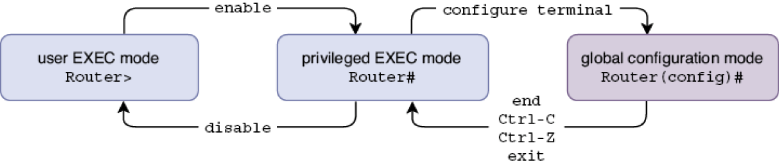
- EXEC Mode: This is the initial mode when first logging into a Cisco device. It provides basic access to the device and allows running simple monitoring and diagnostic commands.
- Privileged EXEC Mode: This mode provides more advanced commands to view detailed information about the device. To enter Privileged EXEC Mode, type
enablefrom EXEC Mode. To exit Privileged EXEC Mode, typedisableto return to EXEC Mode. - Global Configuration Mode: This mode allows modification of the system configuration. To Global Configuration Mode, type
configure terminalorconf t(shorthand). To return to Privileged EXEC Mode, typeendorexit.
6. Ethernet LAN Switching
Ethernet Frame Format
An Ethernet frame is the fundamental unit of data transmission in Ethernet networks. It is used to encapsulate and transmit data over a Local Area Network (LAN). The Ethernet frame format is defined by the IEEE 802.3 standard and consists of several fields. Here is a detailed breakdown of the Ethernet frame format:
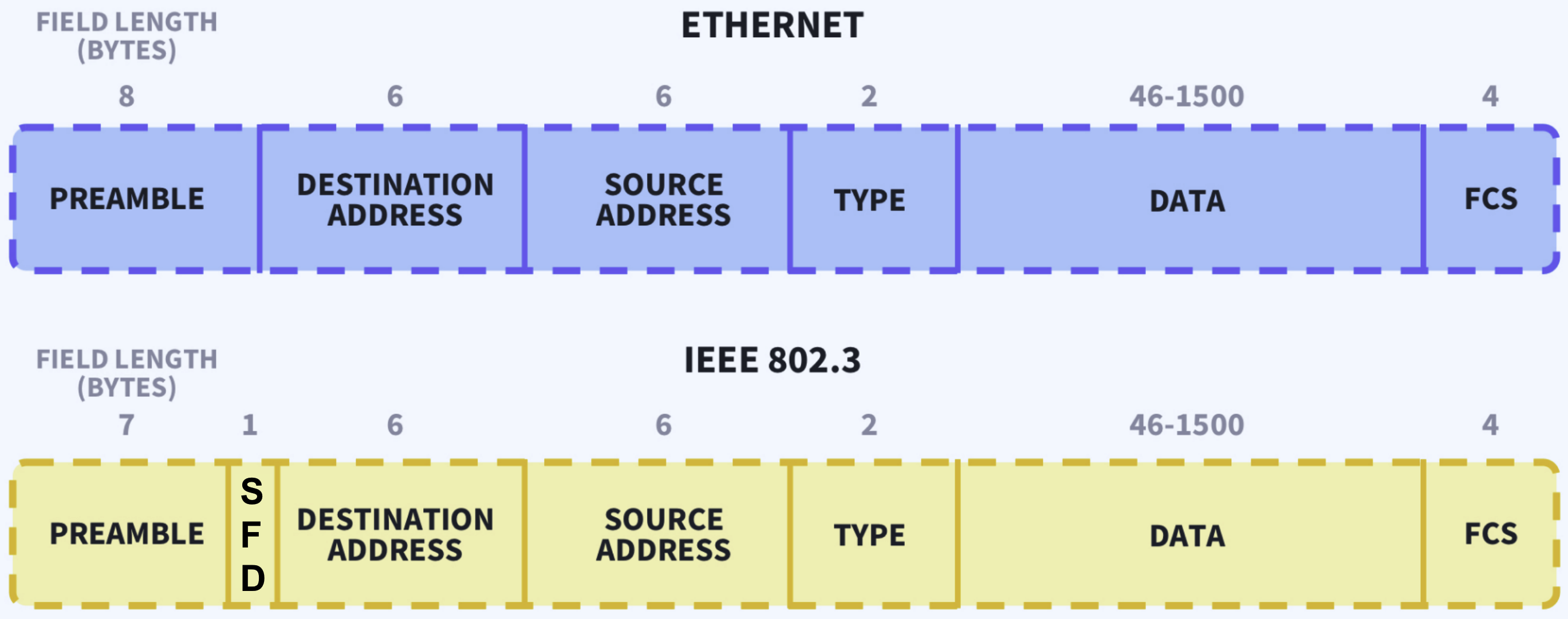
- Preamble (7 bytes): A series f alternating 1s and 0s used for synchonization.
- SFD (Start Frame Delimiter, 1 byte): Uses a one byte bit pattern (
10101011) to mark the end of the preamble and the start of the actual data. - Destination MAC Address (6 bytes): The MAC address of the device receiving the frame.
- Source MAC Address (6 bytes): The MAC address of the device sending the frame.
- EtherType/Length (2 bytes): Indicates the type of protocol (e.g., IPv4, ARP) or the length of the payload.
- Payload/Data (46 - 1500 bytes): The actual data being transmitted, such as an IP packet or other protocol data.
- FCS (Frame Check Sequence, 4 bytes): A 32-bit CRC (Cyclic Redundency Check) for error detection.
Note that the Ethernet header includes the Destination MAC Address, Source MAC Address, and Type/Length fields. It does not include the Preamble and Start Frame Delimiter (SFD) fields. The Ethernet trailer only includes the Frame Check Sequence (FCS) field.
MAC Address
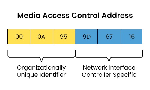
A MAC address (Media Access Control Address) is a unique identifier assigned to a network interface controller (NIC) for communication on a network. It is a 6-byte address, typically represented in hexadecimal format. The MAC address is divided into two parts: OUI (Organizationally Unique Identifier) and NIC (Network Interface Controller) Specific. The OUI is assigned by the IEEE to identify the manufacturer or vendor of the device, while the NIC Specific part is assigned by the manufacturer to uniquely identify the network interface device.
Frame Switching
In computer networks, switches help forward data by using a MAC (Media Access Control) address table. This table stores the MAC addresses of devices connected to the switch and the ports through which those devices are connected.
When a switch receives a data frame, it checks the source MAC address in the frame. The switch then adds the MAC address to its MAC address table and associates it with the port from which the frame arrived. This process is called MAC address learning, and the MAC addresses added in this way are called dynamic MAC addresses.
To keep the MAC address table up-to-date, the switch uses MAC address aging. If the switch doesn’t receive a frame from a particular MAC address for five minutes, it removes that MAC address from the table. This helps avoid outdated or unnecessary entries.
Switches handle two types of frames: unicast and unknown unicast. A unicast frame is addressed to a specific device. If the switch knows the destination device’s MAC address, it forwards the frame to the correct port. This is called a known unicast frame. If the switch doesn’t know the destination MAC address, it treats the frame as an unknown unicast frame. In this case, the switch sends the frame to all its ports, except the one it received the frame on, in an attempt to reach the correct device. This is called flooding.
Here are some common commands for managing MAC address table:
show mac address-table: Shows all learned MAC addresses.clear mac address-table dynamic: Deletes all dynamic MAC addresses.clear mac address-table dynamic address <mac-address>: Removes a specific MAC address.clear mac address-table dynamic interface <interface-name>: Clears MAC addresses on a specific port.
ARP (Address Resolution Protocol)
The Address Resolution Protocol (ARP) helps devices find the MAC addresses of another when they only know its IP address.
ARP works through two key messages: the ARP request and the ARP reply.
- ARP Request: A device sends a broadcast message to
FFFF.FFFF.FFFF, and asks “who has this IP address? Tell me your MAC address!” Since the ARP Request is a broadcast, the switch floods it to all devices in the same boradcast domain. - ARP Reply: The device with the matching IP responds with its MAC address in a unicast message.
A broadcast domain is a group of devices that receive each other’s broadcast messages. If multiple switches are connected, all devices on those switches are in the same broadcast domain.
To avoid sending ARP requests every time they communicate, devices store IP-to-MAC mappings in an ARP table. This table keeps entries for a short time before refreshing them.
Ping
Ping is a widely used utility that helps test the connectivity between two devices on a network. It is part of the Internet Control Message Protocol (ICMP) and is a critical tool for diagnosing network issues and ensuring that devices can communicate with each other.
Ping is part of ICMP (Internet Control Message Protocol) and uses two messages:
- ICMP Echo Request: The sender asks, “Are you there?” by sending a unicast message to the target device.
- ICMP Echo Reply: If the destination device is reachable, it responds with a unicast message confirming connectivity.
Ping is commonly used for troubleshooting network connectivity issues. To use ping, simple type
ping <ip-address>.
7. IPv4
IPv4 Header Format
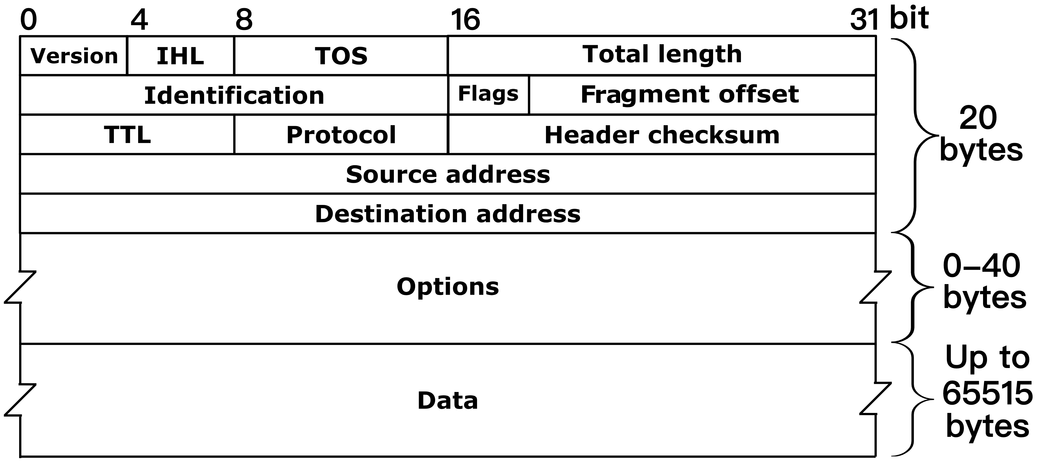
The IPv4 header format consists of several fields that help rout the packet from the source to the destination. Here’s a breakdown of the IPv4 header structure:
- Version: Specifies the version of the IP protocol. For IPv4, the value is
4. - IHL (Internet Header Length): Specifies the length of the header in 32-bit words. The minimum value is 5, which corresponds to a 20-byte header.
- Type of Service (ToS): Defines the priority or quality of service (delay, throughput, reliability) for the packet.
- Total Length: Specifies the entire packet size (header + data) in bytes.
- Identification: A unique identifier for the packet, used for reassembling fragmented packets.
- Flags: Used for fragmentation control. It has the following fields:
- Bit 0 (Reserved): Must be 0.
- Bit 1 (DF - Don’t Fragment): If set, fragmentation is disabled.
- Bit 2 (MF - More Fragments): If set more fragments follow.
- Fragmentation Offset: Specifies the position of the fragment’s data in the original packet. It is used for reassembling fragmented packets.
- TTL (Time To Live): Specifies the maximum number of hops the packet can traverse before being discarded. Decrease by 1 at each hop.
- Protocol: Specifies the protocol used in the data portion of the IP packet, such as:
1for ICMP6for TCP17for UDP
- Header Checksum: A checksum value used for error-checking the header to ensure it has not been corrupted.
- Source IP Address: The IP address of the source of the packet.
- Destination IP Address: The IP address of the intended destination of the packet.
- Options: Optional fields for additional settings, such as security, timestamp, and routing information. Requires padding to align to 32 bits.
IPv4 Addressing
IPv4 addresses are 32-bit numbers that identify devices on a network. They are written in dotted decimal notation (e.g., 192.168.1.1), divided into four groups of 8 bits called octets. An IPv4 addresss is split into two parts: the network portion and the host portion.
- Network Portion: This part identifies the network where a device belongs. All devices in the same network share the same network portion.
- Host Portion: This part identifies the specific device in the network. Each device has a unique host portion.
The network portion is usually indicated with a prefix (e.g.,
/24), which shows how many bits are used for the network. Alternatively, a netmask (e.g.,255.255.255.0) can also define the network portion. A netmask uses 1s for the network part and 0s for the host part.
The IP addresses can be categorized into three types: Network Address, Broadcast Address, and Usable Addresses.
- Network Address: The first address in a network (host portion is all 0s). It identifies the network and can’t be assigned to a device.
- Broadcast Address: The last address in a network (host portion is all 1s). It’s used to send messages to all devices in the network. However, to send a message to all hosts on the local network, the address
255.255.255.255is usually used. - Usable Addresses: These are the addresses that can be assigned to devices. The number of usable addresses is calculated as $2^y - 2$, where $y$ is the number of bits in the host portion. Subtracting 2 accounts for the exclusion of the network address and the broadcast address.
IPv4 addresses can be organized into five classes: A, B, C, D, and E.
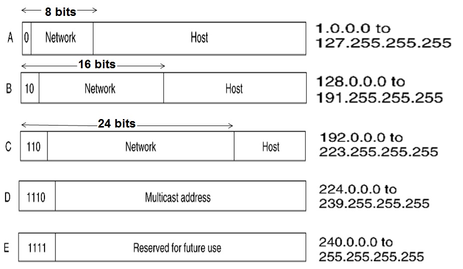
- Class A: For large networks. (First octet: 0-127, uses a
/8prefix) - Class B: For medium-sized networks. (First octet: 128-191, uses a
/16prefix) - Class C: For small networks. (First octet: 192-233, uses
/24prefix) - Class D: For multicast addresses.
- Class E: For experimental purposes.
Note that the classful addressing are obsolete, most modern networks use classless addressing (e.g.,
192.168.1.0/28).
Configuring IPv4 Addresses On a Router
Routers use interfaces with IPv4 addresses to commnunicate between networks. Here are some common use commands:
show ip interface brief: Shows a summary of interface statuses and their IP addresses.show ip interface [interface-name]: Shows detailed settings for a specific interface.no shutdown: Enables an interface (router interfaces are turned off by default.)ip address [ip-address] [netmask]: Assigns an IP address and a subnet mask to the interface.